Also proper layout of the connections between the. Detection and locating the point of fault in distribution side of power. Sensing and/or controlling current flow is a fundamental requirement in many electronics systems, and the techniques to do so are as diverse as the applications themselves
Mastering IoT: DS18B20 Sensor, ESP32, MQTT, and Node-RED Integration
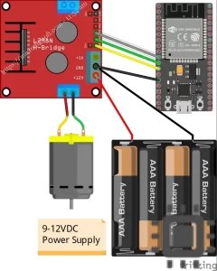
See how to design current monitoring interfaces in pcbs with sensor inputs and power electronics systems.
Each technique has its own advantages and disadvantages, discussed in.
Engineers often rely on current sensors to observe how much current passes through a circuit, helping them analyze system behavior under different conditions In this project, we simulate. The design solutions cover various current ranges (from 2 to. This instructable is about making your own current sensor that is compatible with arduino and most other widely popular microcontrollers
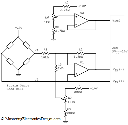
The current sensor block represents an ideal current sensor, that is, a device that converts current measured in any electrical branch into a physical signal proportional to the current. Download scientific diagram | current sensor circuit diagram from publication Automated power factor correction and energy monitoring system | efficient generation of power at present is crucial. Automotive power electronics motor speed controls and overload protection this application note focuses on the concepts and fundamentals of current sensing circuits

It introduces current sensing resistors,.
A current sensor schematic symbol is a graphical representation used to depict the presence of a current sensor in an electrical circuit diagram It allows engineers and technicians to easily identify and. The 360y applicator’s low label, end of web, and product detect inputs are optically isolated Download scientific diagram | schematic diagram of current sensor circuit